The useful definition
Gain staging means managing signal level from one stage to the next so each device operates as intended. In an analog chain that includes noise floor and limited headroom. Inside a modern DAW, it mostly means protecting inputs and outputs, keeping nonlinear processors predictable, and leaving the main bus free to breathe.
Ableton documents that Live’s 32-bit floating-point engine gives internal tracks enormous headroom. A red channel meter therefore does not automatically mean the internal audio has been destroyed. The risk becomes concrete when the signal reaches a fixed-point export, a physical converter output, or a processor with its own clipping or nonlinear behavior. The Main meter is an important warning, but a floating-point bus can retain values above 0 dBFS until a later trim. A floating-point file can also preserve such overs; it cannot repair clipping that already happened earlier.
Original JDMEET signal-flow diagram based on the routing and headroom behavior documented in the Ableton Live 12 Mixer manual.
Why the fader is not the whole answer
A track fader usually changes level after the device chain. Pulling it down can stop the mix bus from clipping while leaving a saturator, compressor or clipper overloaded upstream. If the tone changes when a plug-in is bypassed—even after you match output loudness—the level hitting that plug-in is part of the sound.
Use clip gain, an instrument output, or a clean utility/trim before the processor to control its input. Use the processor’s output control to compensate for level it adds or removes. Use the channel fader to balance the processed result against the arrangement.
Gain staging virtual instruments: preserve the performance first
If a rave stab sounds right but hits the next effect too hard, lowering every MIDI velocity is not necessarily a transparent level correction. Velocity can also change the patch’s articulation. In Ableton Analog, for example, velocity can modulate envelope level and attack time, while the filters have their own saturation stages. This is a named example, not a rule for every VST: inspect the particular instrument and preset.
| Control | What changes | Main caution |
|---|---|---|
| MIDI velocity | Performance data interpreted by the patch. | Timbre or attack may change along with level. |
| Internal oscillator level or drive | A stage inside the instrument. | It can alter processing before the sound reaches the DAW. |
| Instrument output | The level leaving the instrument, when documented as such. | A control named Volume does not prove its position in every plug-in. |
| Clean audio trim after the instrument | The level delivered to subsequent audio effects. | It cannot undo distortion already created inside the instrument. |
Live’s device order separates MIDI processing before the instrument from audio effects after it. Image-Line documents channel-volume controls and velocity-linked modulation as distinct functions. Do not assume every native or third-party instrument responds identically to host controls.
A fixed-source stab comparison
- Keep the performance. Use a fixed MIDI phrase with its busiest chords and overlapping releases. Once articulation works, capture one clean audio pass before external effects, retaining the tail.
- Hold the source constant. Compare that same recording through the target saturator with and without a reduction from a clean pre-effect trim. Compensate cautiously immediately after the saturator; leave its settings unchanged and monitor quietly. Reusing one pass avoids fresh oscillator or modulation variations becoming another variable.
- Listen at similar perceived loudness. Compare attack definition, chord separation and release texture. If the captured source is already unintentionally distorted, return to the instrument’s internal signal path first.
This is a diagnostic to try, not a reported measurement. It isolates downstream processing; it does not test changes inside the live instrument. There is no universal synth-output meter target: preserve the chosen performance and feed the next processor appropriately.
Where to put the trim in FL Studio and Ableton Live
For an ordinary serial insert chain, put one clean level control before the processor you want to drive and another immediately after it. The first changes what that processor receives; the second lets you compare its result at a sensible monitoring level. The diagrams above describe this order, not a particular plug-in interface. Parallel racks, sends and sidechains require checking their separate routes.
FL Studio: use the effect-slot order, not the Mixer fader
Load Fruity Balance in a slot above the target effect, keep Balance centred, and use Volume to reduce the level entering it. A second instance below that effect can compensate the processed level. Image-Line documents top-to-bottom slot processing; its Mixer fader follows the effects. Moving that fader will not reduce the drive into an earlier insert.
For this diagnostic, keep the host effect-slot mix fully wet and hold the processor’s own mix setting fixed. Changing the slot mix blends dry and processed audio; it is not an input trim and would change a second variable in the comparison.
Ableton Live: place Utility around the audio processor
Put Utility immediately before the target audio effect and adjust Gain. On a MIDI track, this belongs after the instrument, where the signal is audio. Add another Utility immediately after the effect for level compensation, leaving stereo and polarity settings unchanged. Keep the track Volume control for balancing the channel; use the pre-effect Utility when the goal is to change the processor’s input.
Kick-loop check: at quiet monitoring level, repeat the same kick phrase, lower only the pre-effect trim, then compensate cautiously with the post-effect trim. Keep automation and downstream nonlinear processing out of this comparison. Listen for transient sharpness, tail density and abrasive upper harmonics at similar perceived loudness. If only the quieter version seems cleaner, recheck the level match. This is a listening procedure, not a claim of a new DAW measurement.
For a concrete example, the JDMeet Phantom signal-flow guide explains why Auto Gain, global Mix and output clipping need separate checks. Identify the stage you are changing instead of assuming automatic compensation guarantees an equal-loudness comparison.
Find the first stage that changes the sound
Follow one path from the source to the output. Compare immediately before and after each processor, with monitoring kept quiet and comparison levels matched. A red meter tells you where to investigate, not which earlier stage is responsible.
- Clean floating-point bus over: if the signal has only been summed or scaled, a clean trim before the next bounded stage can preserve the waveform while reducing level. Check every insert between the over and the trim.
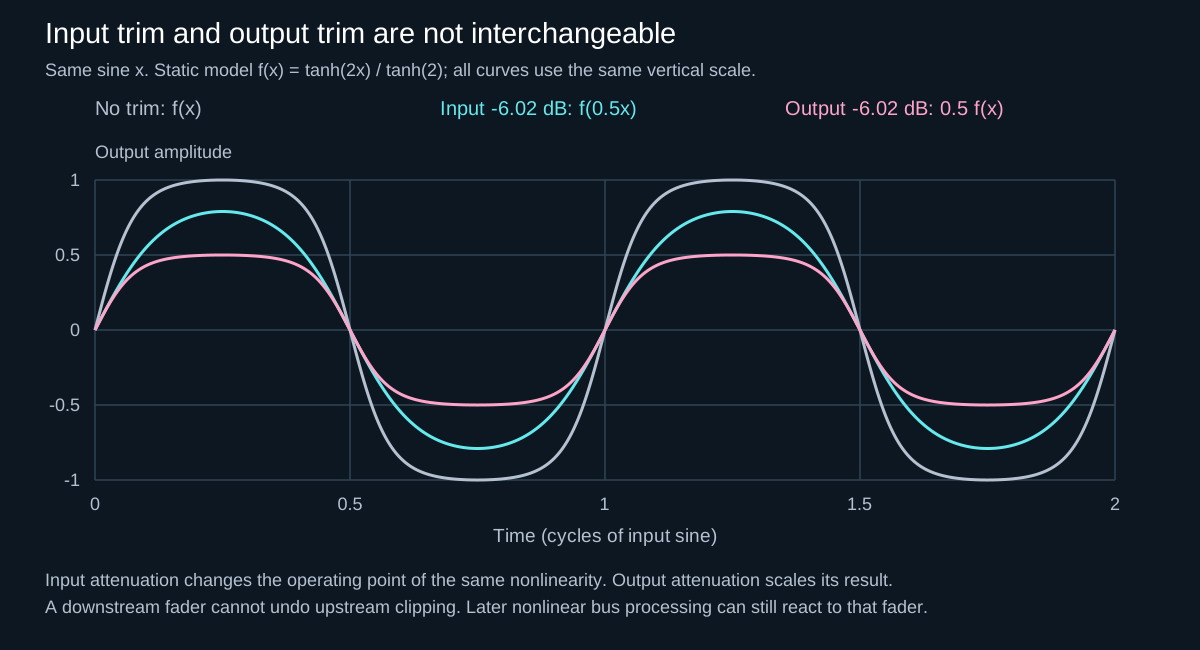
- Unwanted distortion inside an insert: reduce the level entering that processor or change its drive/threshold. Pulling down a later fader only makes the existing distortion quieter. The nonlinear processing guide explains why input drive and output trim are not interchangeable.
- Clipped recording or fixed-point file: lowering playback gain does not restore the original peaks. Return to a clean source or re-record when possible; a quieter damaged file is still damaged.
- Too much limiting without an overload: inspect gain reduction as well as peak meters. If you wanted more transient contrast, revise the limiter or its input rather than only lowering its output. For envelope control, see attack, release and ratio.
A hard-techno workflow
- Start with the raw source. Loop the loudest representative section, not an unusually quiet intro. Check kick layers, rumble returns and synth stacks separately.
- Set the first trim before sound-changing processors. Leave enough room for later boosts and summing. If a plug-in specifies an analog reference level, use that manual and the matching meter convention. Do not treat a −18 dBFS peak, RMS reading and a 0 VU calibration as interchangeable. Listen for the processor’s intended response.
- Level-match every tonal decision. After distortion, compression or clipping, adjust output so bypassed and processed versions feel similarly loud. Then judge punch, density and texture instead of loudness.
- Check buses as sources accumulate. Summing individually safe channels can push a bus above 0 dBFS or drive a nonlinear bus insert harder. A floating-point meter over is not itself proof of destructive clipping. Correct the feeding channels or a clean pre-bus trim before relying on the bus fader.
- Keep the Main path honest. Temporarily bypass loudness processors and confirm the mix still has headroom. Follow the mastering engineer’s delivery specification. There is no mandatory −6 dBFS premaster peak: the important boundary is no unintended clipping, preserved dynamics and a suitable file format.
Why −18 dBFS and floating-point headroom are different claims
The sources address different boundaries. Ableton describes the numerical headroom inside its mixer. The iZotope gain-staging article also describes a particular analog-modelled and hybrid workflow with chosen calibration levels. A processor’s reference level is about its intended operating behaviour; it is not the maximum number a floating-point mixer can store. Neither establishes one correct peak level for every kick, VST or export.
Read the individual processor’s calibration and metering convention. A short click and a sustained tone with equal sample peaks can produce very different average readings. A 0 VU alignment is not permission to replace a VU reading with a peak reading bearing the same dBFS label. For our hard-music workflow, the practical rule is to preserve an input level when its tone works, then manage the output separately.
Distortion makes level a creative control
On a 180 BPM kick, raising the signal into a clipper can thicken the body, flatten the transient and add upper harmonics at once. That may be the goal. The gain-staging mistake is not “driving it too hard”; it is failing to notice that input level moved the signal into a different region of the same distortion curve.
Turn the input down, raise the processor output to match, and compare. Listen for the front edge, low-end length, harshness above the kick body and how much space remains for the vocal or synth. Choose the drive amount because the texture works in the track—not because the meter reaches a fashionable number.
Peak, average and perceived loudness answer different questions
- Peak level warns how close a signal comes to the digital ceiling.
- Average level better describes sustained energy hitting many analog-modelled processors.
- Perceived loudness helps make fair bypass comparisons, but depends on spectrum and time.
A short distorted kick can show a high peak while carrying less average energy than a dense rumble. Do not force both into the same reading. Give each stage the information it needs.
Common failure modes
- Everything at maximum: summing removes bus headroom and makes every nonlinear device react aggressively.
- Master fader rescue: lowering the last fader hides upstream overload without changing it.
- Preset calibration ignored: an analog-modelled chain receives a radically different level from the one its behavior assumes.
- No matched bypass: a louder processed signal is mistaken for a better one.
- Limiter always active: arrangement and balance choices are made against hidden gain reduction.
Good gain staging does not make a record quieter. It makes every loudness decision deliberate.
A controlled internal-headroom experiment
This is a procedure for your own session, not a claim that we measured your DAW or plug-ins. Use a copy of a short, fixed kick loop in an isolated test project. Mute hardware monitoring while configuring it, disable sends and external routing, and never route the boosted intermediate signal to an interface output.
- Establish a reference. Keep the same source file, start sample, sample rate, fades, pan and fader settings for both paths. Disable time-stretching, random modulation and unrelated processing. Do not add a limiter to the comparison bus.
- Test gain and its inverse. With playback stopped, set a downstream clean trim to −24 dB first, then place a +24 dB clean gain before it. These are illustrative test values, not recommended mix levels. An input peaking at −12 dBFS would reach +12 dBFS between these two stages and return to −12 dBFS after them in the ideal linear calculation. Export only the post-trim result as 32-bit float, with normalization and dither off for this diagnostic.
- Compare the rendered result. Align it sample-for-sample with the reference, invert the polarity of one copy on both channels, and sum at identical levels. The residual should be very small if the route only scaled the audio and remained floating-point. A gain operation need not be bit-perfect, so do not demand an invented residual threshold. If cancellation is poor, check alignment, fades, pan, routing and hidden processing before blaming the engine.
- Introduce a known nonlinear stage. Put a fully wet clipper between the gain and inverse trim and drive it into clipping. Keep its output below overload after the trim. Render again, compensate any latency and repeat the comparison. The output trim cannot undo the changed waveform. Listen to the normal, level-matched versions—not an aggressively amplified residual—to judge whether the new texture is useful.
Interpretation: cancellation checks equality under the stated conditions, not sound quality. A residual can come from latency, noise, rounding or intentional processing; its existence alone does not identify clipping. Conversely, a clean result here does not certify every plug-in, fixed-point export or physical converter. The calculated waveshaper figure above illustrates a different, complementary question: moving attenuation before a nonlinearity changes the shape, whereas attenuation after it only rescales that shape.
Ableton’s Audio Fact Sheet distinguishes 64-bit summing from its 32-bit internal processing. Its cancellation tests also depend on controlled rendering and playback conditions; bit-depth labels do not replace a signal-path check.
Sources and further reading
- Ableton Analog — Velocity modulation, filter saturation and global output
- Ableton Live 12 — MIDI and audio device order
- Image-Line — Channel level and velocity/keyboard tracking
- Ableton Live 12 Reference Manual — Mixing and floating-point headroom
- Image-Line — Mixer faders and pre/post-effect signal flow
- Image-Line — Effect-slot order and wet/dry mix
- Image-Line — Fruity Balance Volume and Balance controls
- Ableton Live 12 Audio Fact Sheet — Summing, rendering and cancellation tests
- iZotope — Gain staging: what it is and how to do it
- iZotope — Preparing levels and headroom for mastering
- Ableton Live 12 — Audio effects, input gain and output level